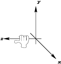
A left-handed coordinate system
Enter Perl, stage left. Portable. Compilable. Powerful. Couple it with OpenGL and you have a match made in heaven for rapid 3D development.
Before we delve into the soupy, steaming innards of 3D graphics and OpenGL, we ought to explain some of the concepts needed for 3D graphics programming. The three-dimensional space we're used to can be navigated in any of three directions: up/down, left/right, and forward/backward. The premise of Euclidean 3D space is exactly the same, although it requires more precision than "up and left a bit", or "a few yards backward." Imagine being blindfolded in a large field with a tree near the middle and have a friend direct you to that tree. Difficult? Try it and see! Even the simple matter of "forward" becomes a relative concept with different meanings depending on the person's orientation. We need to establish some ground rules.
First, we need to define our origin, the central reference point in the 3D space. Everything we describe is relative to this point. The origin is usually dubbed (0, 0, 0) in our coordinate system.
A left-handed coordinate system
So how do we agree which direction corresponds to which axis in our coordinate system? This requires the creation of another concept known as the handedness of a coordinate system. Coordinate systems can be either left-handed or right-handed. Wrap your hand around the Z-axis, with your thumb pointing along the Z-axis and the X-axis running back along your arm. If you had to use your right hand, you're in a right-handed coordinate system.
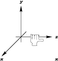
A right-handed coordinate system
Right-handed coordinate systems are more common in today's applications, yielding the following directions:
Axis	Direction
X-axis	right
Y-axis	up
Z-axis	backward
For the programmer looking at the screen:
Axis	Direction
X-axis	Screen right
Y-axis	Screen top
Z-axis	Toward user
Now that we've sorted out the framework of our space, we can look at how to fill it.
Graphical primitives are the most basic components that can be used by a 3D graphics system. These range from the fairly obvious to the not-so-obvious. We shall deal with these in turn.
The Vertex. Any discrete point in 3D space is called a vertex. The origin is a vertex because it's a point at (0, 0, 0).
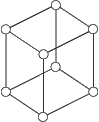
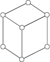
Vertices by themselves are only partly useful, since by themselves they create only a "point cloud", which is fairly useless for discerning objects in. Consider the figure below.

Do these five vertices form a star, a pentagon, or something else? It's impossible to be sure, since it all depends on how your perceive it. That's an inherent problem with point cloud rendering; it's nigh-impossible to construct any sort of coherent impression from points alone. They can be used to render real clouds, but that's about it.
The Line. Lines are the building blocks of wireframe models, a staple of 3D graphics. On a slow computer, they provide a quick way to render scenes. If you want to see through objects, they let you do that as well. They are of most use in CAD tools, where the designer needs to be able to manipulate any part of the design. If the model were solid, they wouldn't be able to see all of it at once.
Lines allow us to depict the edges of an object, which helps the viewer's brain assign meaning to the picture on the screen. But for rendering solid objects, polygons are preferable.
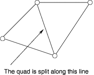
The Polygon. Polygons are 2D surfaces bounded by vertices. Triangles are polygons with three vertices; squares, rectangles and other quadrilaterals are polygons with four vertices, and so on. Polygons must always be flat (or planar) - all the vertices must lie on the same plane. Polygons that are non-planar are usually automatically split up into smaller planar polygons by the rendering software. In many rendering libraries, including OpenGL, polygons with more than three vertices are split into triangles. This process of polygon-splitting is referred to as tesselation, where large complicated polygons become sets of smaller polygons that aren't necessarily triangles, or triangulation where larger polygons are split completely into triangles.(OpenGL doesn't actually perform automatic triangulation of polygons, but you can use its GLU routines to do that.) That's quite a mouthful, so let's look at a diagram that illustrates the principles. The figure below shows a quadrilateral and how it might be triangulated.
Polygons are the most common tool for rendering 3D graphics, since they can be filled to produce solid-looking objects. Now that we're armed with the basic concepts of three-dimensionality, we can address how to render scenes on screens.
Drawing things on the screen is the whole point of graphics. But how do we get our collection of points and polygons onto the screen? And what will it look like? Will it look realistic? All simple questions with complicated answers.
To make any headway into this subject, we need to introduce a few more concepts: the viewport, the view frustum, and perspective.
The Viewport. The viewport is our window onto our 3D world. Imagine standing at the window of your house, looking out onto the world outside. That's your viewport. We'll only discuss rectangular viewports for the moment, which means we can assume that the viewport can be described by a width and a height. How do we work out what we're looking at in the world, and how do we translate that into the boundaries of this viewport? To accomplish this, we need to consider the view frustum.
The View Frustum. The view frustum enables our rendering engine to work out what the user can see through their viewport onto the world. To help envision this, consider the figure below:
)
The View Frustum
The view frustum is pyramid-shaped, with the apex positioned at the eyes of the viewer. To use our house window analogy, the eyepoint of the view frustum is right between our eyes as we look out the window. The other two planes we'll discuss in a later section, but the far clipping plane can be considered the base of the pyramid, and constitutes the farthest distance at which we can see objects in the world. Anything farther is invisible.
Hopefully you can orient this diagram in your mind's eye as if you were looking through the window outside. The edges of the pyramid depicted in dashed lines extend from your eyes through each corner of the viewport until they intersect with the far clipping plane. From knowing these points of intersection with the pyramid base, we could calculate the dimensions of the base if we desired.
Fine, so now we know what we can see in the world, but how do we translate that onto the viewport? How can we resolve those 3D objects into 2D objects for displaying on our screen? The answer is simple, and one known by artists for centuries.
Perspective. Perspective is an optical effect that makes identically sized objects far away from us appear smaller than objects nearby. Therefore, with perspective, we can judge distance between two objects by the difference in apparent size.
)
The Vanishing Point
We project perspective towards a vanishing point, a point on the horizon at which all objects converge. That's the opposite of our view frustum, which converges squarely between the user's eyes.
Not to despair. We can still tackle the vanishing point perspective - we just need to think of it back-to-front. We project the objects away from the horizon and toward the eyepoint. But what do we project? The vertices, of course. Once the vertices have been mapped onto the viewport, the polygons will automatically be projected too, since they're defined by their vertices. In OpenGL, a polygon has no knowledge of where it is - it only knows what it is constructed from. Therefore, if we can calculate the projection from a three dimensional coordinate system onto a two dimensional coordinate system, we can determine where our objects should lie on the viewport.
And, that, in a nutshell, is how we convert our three dimensional world into something we can view on a two dimensional screen!
Now, on to the fun part: techniques for representing objects on the screen. These different drawing techniques are called rendering pipelines, and constitute the gory innards of any graphics engine. They can be implemented in either software or hardware.
Rendering Pipelines. At this point, we have a good idea of what we want to draw, and where on the screen we want to draw it. The big question is, how do we draw it? Do we draw it as lines, filled polygons, or with some other funky technique? We'll now discuss the various rendering pipelines available to today's programmers.
Wire-frame pipelines are generally the fastest pipeline in graphics engines, since painting pixels is usually the slowest part of any rendering pipeline, and we're painting a lot less here than we would if our polygons were filled.
There are, however, a few additional things we can do to our wire-frame pipeline to make it more realistic, without slowing it down too much. We could use a technique called depth-cueing, which darkens the lines as they get further away from the viewport. This heightens the perception of depth and is a very useful technique. A second and more complex technique is hidden-line removal, which makes objects appear solid. A cube rendered with hidden-line removal is shown below.
An important aspect of a filled pipeline is that each polygon can be given a different brightness, implying the orientation of that polygon to the source of light. For example, if we hold a toaster near a light bulb, the parts of the toaster facing the bulb will be brighter than those facing away from the light. Hidden-line removal can't simulate this, making "filled" pipelines a better choice. The figure below illustrates a flat-shaded Utah teapot. (Martin Newell's Utah teapot is widely used as a test object for rendering engines. [So widely used that you'll see it again in Steve Lidie's article nine pages from now. -ed]) A light shines from the viewport towards the teapot, causing the polygons in the center to appear brighter than those on the sides.
)
This approach is slightly more time-consuming than the simple uniform color filling flat-shaded pipeline, but the effects are spectacular. Objects that previously looked blocky now have the appearance of being curved, as can be seen below in the Utah teapot with Gouraud shading.
)
The basic purpose of texture mapping is to allow the artist to create realistic looking surfaces, such as a stone wall, with a minimum of computation. You could do without texture mapping, modeling each individual stone using points and polygons. Or you could simply map the texture of some stones onto a single flat polygon. That's texture mapping.
Anyway, you now know enough of the theory involved in 3D graphics to be dangerous, so let's take a look at the rendering engine we're going to be using: OpenGL.
OpenGL is a powerful and elegant 3D graphics API developed by SGI. It provides platform-independent mechanisms to let you to manipulate the graphical primitives discussed earlier, and has an unofficial extension library providing programmers with standard routines for platform-dependent tasks such as the manipulation of windows and the handling of window events. Even though these libraries are not officially part of OpenGL, they're found with most OpenGL implementations.
The OpenGL architecture is basically a large state machine: you call pull levers at any point in the execution of the machine to alter any subsequent operations the machine may execute. For example, if we were rendering a cube comprised of six polygons, and had already rendered three of these polygons with a flat-shaded pipeline, we could then make a single function call to pull a lever in the state machine and render the final three with a smooth-shaded pipeline instead.
Brian Paul's superb Mesa, an OpenGL-like library, makes possible OpenGL programming on lower-end PCs. Mesa provides an almost fully-featured OpenGL implementation (although not a licensed one, so it can't call itself OpenGL). Currently at version 2.1, it's fast and stable.
Keeping pace with Mesa is Stan Melax's Perl OpenGL module, which provides access to most OpenGL functions. The module's speed is comparable to compiled C code, but allows for the ease of use we have come to know and love from Perl!
Since the readership of this article are probably champing at the bit to get on with some groovy Perl hacking, let's discuss how to use the OpenGL module.
Creating a Viewport. The first thing we need to do is create our viewport. The OpenGL module provides glpOpenWindow(), a useful method that pops up a GL canvas for us. It also handles some of the icky stuff like allocating colors. The following short example creates a default window for us.
1  #!/usr/bin/perl -w
2  #
3  # Creates a GL viewport
4
5  use OpenGL;
6
7  glpOpenWindow();
8
9  print "Press return to exit\n";
10
11 while ( <> ) {
12     exit;
13 }
You'll notice that the window is empty. And if you move it around, it'll never redraw. Not so useful. What we need to do now is create the view frustum, so that OpenGL will at least have some clue about what it's going to be rendering.
Creating the View Frustum. The example code below provides OpenGL with an idea of where you want objects to be in the world, and how it should project those objects onto your viewport.
1  #!/usr/bin/perl -w
2  #
3  # Creates a GL viewport and view frustum
4
5  use OpenGL;
6
7  sub glInit {
8      # Creates the OpenGL viewport to render into
9      glpOpenWindow();
10
11     # Creates the view frustum, with near clipping
12     # plane at z = 1 and far clipping plane at z = 20
13     glMatrixMode( GL_PROJECTION );
14     glFrustum(-1.0, 1.0, -1.0, 1.0, 1.0, 20.0);
15 }
16
17 ### Main program body
18
19 # Initialize any GL stuff
20 glInit();
21
22 print "Press return to exit\n";
23
24 while ( <> ) {
25     exit;
26 }
In the listing above, lines 13 and 14 are the most important. Line 13 pulls the lever in the OpenGL state machine that says "Any operations from now on alter my idea of the view frustum." These operations might be matrix arithmetic if we needed to scale or rotate our view frustum. Line 14 defines the frustum itself, by fixing the coordinates of the viewport corners and the near and far clipping planes.
However, after running the script, you'll see the same thing as before. A window containing nothing, and that won't redraw.
Drawing objects in OpenGL is relatively simple. We need a method that redraws the screen and all of the objects on it. This sounds quite intensive, but OpenGL is a state machine-based rendering engine, which means that a good majority of the work is already done for us.
To begin drawing, we change the MatrixMode from GL_PROJECTION to GL_MODELVIEW to calculate matrix operations from our viewpoint, and define a display() method that will be invoked when the screen needs to be redrawn.
1  #!/usr/bin/perl -w
2
3
4  use OpenGL;
5
6  ### Initialization function
7  sub glInit {
8
9      # Create the viewport
10     glpOpenWindow();
11
12     # Define the view frustum
13     glMatrixMode( GL_PROJECTION );
14     glFrustum(-1.0, 1.0, -1.0, 1.0, 1.0, 20);
15
16     # Prepare to specify objects!
17     glMatrixMode( GL_MODELVIEW );
18 }
19
20 ### Display callback
21 sub display {
22
23     # Make sure we're smooth-shading now, so
24     # we can to blend the colors of the
25     # background polygon.
26     glShadeModel( GL_SMOOTH );
27
28     # Draw graded black->blue polygon first
29     glBegin( GL_POLYGON );
30     glColor3f( 0, 0, 0 );
31     glVertex3f( -20, 20, -19 );
32     glVertex3f( 20, 20, -19 );
33     glColor3f( 0, 0, 1 );
34     glVertex3f( 20, -20, -19 );
35     glVertex3f( -20, -20, -19 );
36     glEnd();
37
38     glFlush();
39     glXSwapBuffers();
40 }
41
42 ### Main body of program
43
44 glInit();
45 display();
46
47 print "Press return to exit\n";
48
49 while ( <> ) {
50     exit;
51 }
This program is a little more involved! The interesting chunk is the display() method between lines 21 and 40, which has OpenGL set the graphics pipeline to be smooth-shading, and then draw a polygon.
After the polygon is begun with glBegin(GL_POLYGON), the next step is to tell OpenGL "Anything I do from now on will be black", as specified by glColor3f(0,0,0). We then create two vertices at the top left and top right of the far clipping plane. Then we switch to blue by calling glColor3f() again with the new RGB value (0, 0, 1). Finally, we create another two vertices of the polygon at the bottom right and bottom left of the far clipping plane, and then tell OpenGL that we have finished specifying that polygon with glEnd().
Lines 38 and 39 contain two commands to flush the graphics pipeline, resulting in the viewport being filled with a smoothly-shaded polygon, as shown below.

And that's how we draw objects in OpenGL.
Some Viewport Tricks. You may have noticed that the viewport filled in this way:
This is quite a disturbing effect. Now, if you run the example program called planespin on the TPJ web site, you can see the plane flickering and various visual artifacts appearing. This is horrible! What can we do?
Well, OpenGL supports double buffering, which means that instead of having only one buffer for your viewport, you have two. You render onto the off-screen buffer, and when rendering is complete, that buffer is swapped with the on-screen buffer. This completely eliminates the flickering, and with very little overhead. If you alter the glpOpenWindow() as follows, double-buffering will be enabled.
glpOpenWindow(attributes => [ GLX_RGBA, GLX_DOUBLEBUFFER ]);
We can also use other parameters with the glpOpenWindow() call, such as the width and height of the viewport. For example,
glpOpenWindow(width => 200, height => 200,
               attributes => [ GLX_RGBA, GLX_DOUBLEBUFFER ]);
creates a 200x200 double-buffered viewport for you.
Viewport Resize Issues. What happens if we resize the viewport in planespin? The actual window resizes, but the viewport doesn't. Yuck. We really ought to handle these events gracefully.
Stan's solution in the Perl OpenGL module is to add event handlers for certain events that we want to trap. We first need to add another parameter to glpOpenWindow() informing the viewport which events to keep, and which to discard. In the case of resizing the viewport, we wish to know only about StructureNotify requests, so the corresponding call is:
glpOpenWindow( width => 300, height => 300,
          attributes => [ GLX_RGBA, GLX_DOUBLEBUFFER ],
          mask => StructureNotifyMask );
The mask is a bit vector, so if we wished to trap keyboard events as well, we'd bitwise OR StructureNotifyMask with KeyPressMask:
glpOpenWindow( width => 300, height => 300,
               attributes => [ GLX_RGBA, GLX_DOUBLEBUFFER ],
                mask => StructureNotifyMask | KeyPressMask );
We also want to add an event handler for ConfigureNotify requests, which we store in the %eventHandler hash:
$eventHandler{&ConfigureNotify} =
  sub {
      my ( $event, $width, $height ) = @_;
      print "Resizing viewport to $width x $height\n";
      glViewport( 0, 0, $width, $height );
  };
Now, all we need to do is process these events within the main while loop.
# While there are events in the X event queue
while ( $pendingEvent = XPending ) {

    # Fetch the next event in the queue
    my @event = &glpXNextEvent;

    # If we have a handler for this event type
    if ( $s = $eventHandler{$event[0]} ) {

        # Execute the handler
        &$s( @event );
    }
}
And that's all there is to it!
For your delectation and delight, there's a program called paperplane on the TPJ web site that whizzes some paperplane objects around inside the view frustum. It illustrates some of the more useful facets of Perl and OpenGL and is a useful guide to help you navigate the murky waters of 3D programming.
Resources
To allow you to program OpenGL code from within Perl, you'll need the following:
Some literature that budding OpenGL gurus might find of interest:
Thanks, in no particular order, go to: Mark Kilgard for graciously allowing permission to use parts of the paperplane code in this article; Stan Melax for writing the OpenGL module and reviewing this article; Andy Colebourne for reviewing this article and writing the splendid AC3D modeller which helped build many of the example code models.
See http://www.comp.lancs.ac.uk/computing/users/andyac3d.html.
_ _END_ _